
| LM-A CONTROL SYSTEM with 10 adjustable limits for drapes, screens and doors - INSTRUCTION MANUAL | |
|
|
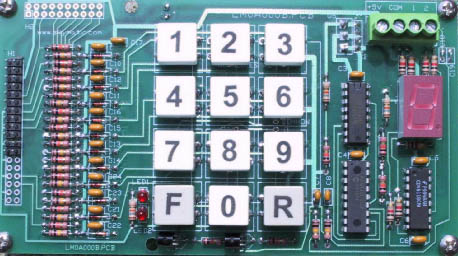 |
FIG.1 |
Logic module LM-A (see Fig.1) expands capabilities of RCB-1, RCB-2, RCB-3 and RCB-6 Control Systems, featuring multiple stop settings for drapes, vertical blinds, doors, and projection screens. LM-A, used in conjunction with an optical encoder mounted on the motor drive, connects directly to RCB system via low voltage ribbon cable (see Fig. 2 below). LM-A allows settings of up to 10 limits. The limits can be controlled from the Keypad, or from the remote control station wired to RCB system. |
|
|
| Power-Up
WHAT HAPPENS (AUTOMATICALLY) ON THE POWER-UP: The Controller retrieves all the previously saved Limits from the Microprocessor's EEPROM memory. During this period (~3 seconds) the 7 segment LED will flash the current software revision number, then it goes blank. The system is now ready for NORMAL OPERATION (see below). Otherwise, proceed to set the MECHANICAL LIMITS. IMPORTANT:Please make sure to set the mechanical limits using F and the R pushbutons on the keypad, and by adjusting respective limit switches on the motor drive. The mechanical limit on the left should be set in the location that becomes Limit '1'. |
|
|
|
|
|
Setting Limit 1 Purpose: To align mechanical and electrical limits How: The drive should be in the Limit'1'. Otherwise, move the drive manually, using Forward or Reverse pushbuttons to mechanical limit 1. To set the limit, press Pushbutton PB 1 and hold it for 5 seconds. When the LED display stops flashing, number 1 on the display becomes steady and the limit is set. |
|
|
|
|
|
Setting Limits 2 Through 9 Purpose: To set the individual limits How: Move the drive manually to desired position using Forward or Reverse pushbuttons. A small LED next to the keypad, will indicate that the motor drive is moving. To set limit number 2, stop the drive in the desired location. Press Pushbutton PB 2 and hold it for 5 seconds. When the LED display stops flashing, number 2 on the display becomes steady and the limit is set. To set the remaining limits, repeat the process by moving the mechanical drive manually using Forward or Reverse pushbuttons into the desired position(s). Then set Limits 3 through 9 accordingly, using PB3 through PB9. (Please note, PB0 is also a legitimate limit. Us it, if you need limit number 10). |
|
|
|
Normal Operation: Purpose: To operate the drive between the preset limits How: Depress the Pushbutton (1 through 9) on the keypad (or close the equivalent remote contact), for 0.5 sec. The motor drive will begin to travel towards that limit. During the travel the LED display will flash the number of the selected limit. Once the drive arrives, the motor stops and the LED number becomes steady. The motor drive, while travelling, can be stopped by momentarily pressing any Pushbutton on the keypad. The limits can be set in random order. However, for easy visualization, we recommend the limits be set in a consecutive order, say, from left to right, starting with Mechanical/Electrical limit '1'. |
|
|
| LIMITED
WARRANTY Skymatic Controls inc. believes in the quality of its products. As a result, Skymatic Controls Inc. warrants that the product is free from defect of material or workmanship when used within specifications. At its sole discretion, Skymatic Controls Inc. agrees to repair, replace or refund the purchase price of the defective product if written notice is received within TWO (2) years of the date of purchase. Shipping costs are to be assumed by the customer. Skymatic Controls Inc. assumes no liability, expressed or implied, beyond the obligation to repair, replace or refund the purchase price of the defective product. This warranty is invalid if the product has been modified, repaired, or altered in any way not authorized previously by Skymatic Controls Inc. in writing. |
|||
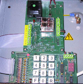 |
FIG. 2 | ||